Learning the STM32 Peripheral library.
I’m not much of a programmer when it comes to bare-metal micro-controllers, but it’s one area or programming I’ve been really interested in for a long time.
I have hoarded quite many different types of development boards to play on, and decided to play around with an STM32 bluepill for a change.
I also had a DTH11 temperature and humidity sensor and an LCD monitor with an I2C connection lying around, so I decided to create a simple program that reads and displays the temperature and humidity in my room.
Previously, I have always used the libopencm3 library when working with STM32 boards.
This time I decided to mix things up a bit, and use an official library provided by ST.
Probably it’s better to use the libraries provided by the vendor, as those are the ones that most likely would be used in a professional environment.
Besides having fun when working on my side projects, one goal of mine is to learn to write professional level software.
That goal is much better addressed by using the professional libraries.
Setting up the development environment
Unfortunately, the default way ST wants you to work is by using their horrible CubeIDE. That’s something I refuse to use when I’m not getting payed, so my first task was to create a Makefile based build environment around the ST libraries.
I opted to use the STM32 Standard Peripheral library for this project.
I was able to find some Makefiles online using this library, and I modified them to suit my own needs. Unfortunately I lost the source where I stole those from.
My version of the Makefile can be found here.
Starting the programming
I started the work like I almost always do when doing embedded projects; blinking an LED.
Nothing fancy, just needed to initialize a GPIO pin as output and then change it’s value.
I created a function for the initialization, and used the library function to change the values:
void init_GPIO_output(GPIO_TypeDef* PORT, uint32_t PIN)
{
    // GPIO structure for port initialization
    GPIO_InitTypeDef GPIO_InitStructure;

    // enable clock on APB2
    if (PORT == GPIOA) {
        RCC_APB2PeriphClockCmd(RCC_APB2Periph_GPIOA,  ENABLE);
    }
    else if (PORT == GPIOB) {
        RCC_APB2PeriphClockCmd(RCC_APB2Periph_GPIOB,  ENABLE);
    }
    else if (PORT == GPIOC) {
        RCC_APB2PeriphClockCmd(RCC_APB2Periph_GPIOC,  ENABLE);
    }

    GPIO_InitStructure.GPIO_Pin = PIN;
    GPIO_InitStructure.GPIO_Mode = GPIO_Mode_Out_PP;    // output push-pull mode
    GPIO_InitStructure.GPIO_Speed = GPIO_Speed_50MHz;   // highest speed
    GPIO_Init(PORT, &GPIO_InitStructure);
}

...

GPIO_SetBits(GPIOC, LED_Pin);
....
GPIO_ResetBits(GPIOC, LED_Pin);
Nice and easy.
The next step was to print something with the UART. This would be useful for debugging the DTH11.
Again, I needed two main functions, an init and a print function.
They were defined as follows:
void init_USART3_output()
{
    RCC_APB2PeriphClockCmd(RCC_APB2Periph_GPIOB, ENABLE);
    RCC_APB1PeriphClockCmd(RCC_APB1Periph_USART3, ENABLE);

    GPIO_InitTypeDef GPIO_InitStructure;
    GPIO_InitStructure.GPIO_Pin = GPIO_Pin_10;
    GPIO_InitStructure.GPIO_Speed = GPIO_Speed_50MHz;
    GPIO_InitStructure.GPIO_Mode = GPIO_Mode_AF_PP;
    GPIO_Init(GPIOB, &GPIO_InitStructure);

    USART_InitTypeDef USART_InitStructure;
    USART_StructInit(&USART_InitStructure);

    USART_InitStructure.USART_BaudRate = 115200;
    USART_InitStructure.USART_StopBits = USART_StopBits_1;
    USART_InitStructure.USART_WordLength = USART_WordLength_8b;
    USART_InitStructure.USART_Parity = USART_Parity_No;
    USART_InitStructure.USART_Mode = USART_Mode_Tx;
    USART_InitStructure.USART_HardwareFlowControl = USART_HardwareFlowControl_None;
    USART_Init(USART3, &USART_InitStructure);
    USART_Cmd(USART3, ENABLE);
}

void USART3_Print(const char* msg)
{
    for (unsigned int i = 0; i < 4098; ++i) {
        while (!USART_GetFlagStatus(USART3, USART_FLAG_TXE));
        USART_SendData(USART3, msg[i]);
        if (msg[i] == 0) {
            break;
        }
    }
    while (!USART_GetFlagStatus(USART3, USART_FLAG_TXE));
    USART_SendData(USART3, '\r');
    while (!USART_GetFlagStatus(USART3, USART_FLAG_TXE));
    USART_SendData(USART3, '\n');
}
I opted to use the USART3 for my UART output. Not for any particular reason really, just decided to choose that.
I created some sleep functions for creating delays of milliseconds and microseconds to my program, and after that, I was ready to start working on the DHT11 sensor.
Reading the temperature and humidity
The DHT11 sensor has its own protocol for communications.
The nice thing about it is that it uses only a single wire for the communication, but as it doesn’t follow any standard protocol (that I know of) the communication needed to be implemented from scratch.
The communication begins by the MCU pulling down the data pin for at least 18ms for starters, and then pulling it up for about 20us.
The sensor responds by keeping the data-line down for 80us, then pulling it up for 80us, and then begins transmitting the data.
In my code, the startup sequence looks something like this:
int DHT11_Read(int* temperature, int* humidity)
{
    uint8_t data[5] = {0};

    init_GPIO_output(DHT11_PORT, DHT11_PIN);
    GPIO_ResetBits(DHT11_PORT, DHT11_PIN);
    mpsdelay(20);
    GPIO_SetBits(DHT11_PORT, DHT11_PIN);
    mpsudelay(24);
    init_GPIO_input(DHT11_PORT, DHT11_PIN);
    while (!GPIO_ReadInputDataBit(DHT11_PORT, DHT11_PIN)) {}
    while (GPIO_ReadInputDataBit(DHT11_PORT, DHT11_PIN)) {}
    // Start reading data
    ...
The sensor sends its data-bits by first pulling the signal low for 50us, then pulls the line up for 26-28us or 70us.
If the line is up for under 28us, the data-bit sent is zero. And likewise, if the line is up for about 70us, the data-bit is a one.
So basically, reading the bit looks something like this:
static uint8_t DHT11_ReadBit()
{
    unsigned int deltaT = 0;

    while (GPIO_ReadInputDataBit(DHT11_PORT, DHT11_PIN)) {
        deltaT++;
    }
    while (!GPIO_ReadInputDataBit(DHT11_PORT, DHT11_PIN)) {}
    return deltaT > ZERO_BIT_MAX_T;
}
And to get a whole byte:
static uint8_t DHT11_ReadByte()
{
    uint8_t output = 0;
    for (int i = 0; i < 8; ++i) {
        output |= DHT11_ReadBit() << (7-i);
        while (!GPIO_ReadInputDataBit(DHT11_PORT, DHT11_PIN)) {}
    }

    return output;
}
With those functions, I was able to finish my DHT11_Read function like this:
    ...
    for (int i = 0; i < 5; ++i) {
        data[i] = DHT11_ReadByte();
    }

    int sum = 0;

    for (int i = 0; i < 5; ++i) {
        if (i != 4) {
            sum += data[i];
        }
    }
    *humidity = data[0];
    *temperature = data[2];

    return sum == data[4];
}
The last byte the sensor sends is a checksum that should equal the sum of all previous bytes.
I’m not sure how accurate the DTH11 module is, but I was able to read values that probably could be the humidity and temperature of my room, and the checksum was correct, so I assume everything’s working like it should.
Displaying the data
After reading the data, it was time for me to try and display it.
I had gotten an LCD1602 module from some Arduino kit, with a PCF8574 I2C driver.
I decided to use the I2C1 port for the communication, and created the following init function, and a function for sending a data buffer:
#define LCD_I2C_ADDRESS 0x4E

static void I2C1_Init()
{
    RCC_APB2PeriphClockCmd(RCC_APB2Periph_GPIOB, ENABLE);
    RCC_APB1PeriphClockCmd(RCC_APB1Periph_I2C1, ENABLE);

    GPIO_InitTypeDef GPIO_InitStructure;
    GPIO_InitStructure.GPIO_Speed = GPIO_Speed_50MHz;
    GPIO_InitStructure.GPIO_Mode = GPIO_Mode_AF_OD;
    GPIO_InitStructure.GPIO_Pin = GPIO_Pin_6 | GPIO_Pin_7;
    GPIO_Init(GPIOB, &GPIO_InitStructure);

    I2C_DeInit(I2C1);
    I2C_Cmd(I2C1, ENABLE);

    I2C_InitTypeDef I2C_InitStruct;
    I2C_StructInit(&I2C_InitStruct);
    I2C_InitStruct.I2C_ClockSpeed = 100000;
    I2C_InitStruct.I2C_Mode = I2C_Mode_I2C;
    I2C_InitStruct.I2C_OwnAddress1 = LCD_I2C_ADDRESS;
    I2C_InitStruct.I2C_Ack = I2C_Ack_Enable;
    I2C_InitStruct.I2C_AcknowledgedAddress = I2C_AcknowledgedAddress_7bit;

    I2C_Init(I2C1, &I2C_InitStruct);
}

static void I2C1_SendBuffer(uint8_t* data, unsigned int size, uint8_t address)
{
    while (I2C_GetFlagStatus(I2C1, I2C_FLAG_BUSY));

    I2C_GenerateSTART(I2C1, ENABLE);
        while(!I2C_CheckEvent(I2C1, I2C_EVENT_MASTER_MODE_SELECT));

    I2C_Send7bitAddress(I2C1, address, I2C_Direction_Transmitter);
        while(!I2C_CheckEvent(I2C1, I2C_EVENT_MASTER_TRANSMITTER_MODE_SELECTED));

    for (unsigned int i = 0; i < size; ++i) {
        I2C_SendData(I2C1, data[i]);
            while(!I2C_CheckEvent(I2C1, I2C_EVENT_MASTER_BYTE_TRANSMITTED));
    }
    I2C_GenerateSTOP(I2C1, ENABLE);
        while(I2C_GetFlagStatus(I2C1, I2C_FLAG_BUSY));
}
After getting the I2C data operations to work, I was able to initialize the LCD screen.
By studying the display data sheet and code from a blog post, I got the LCD screen working through the I2C module.
The final step was to just combine reading the sensor data and printing it to the LCD display:
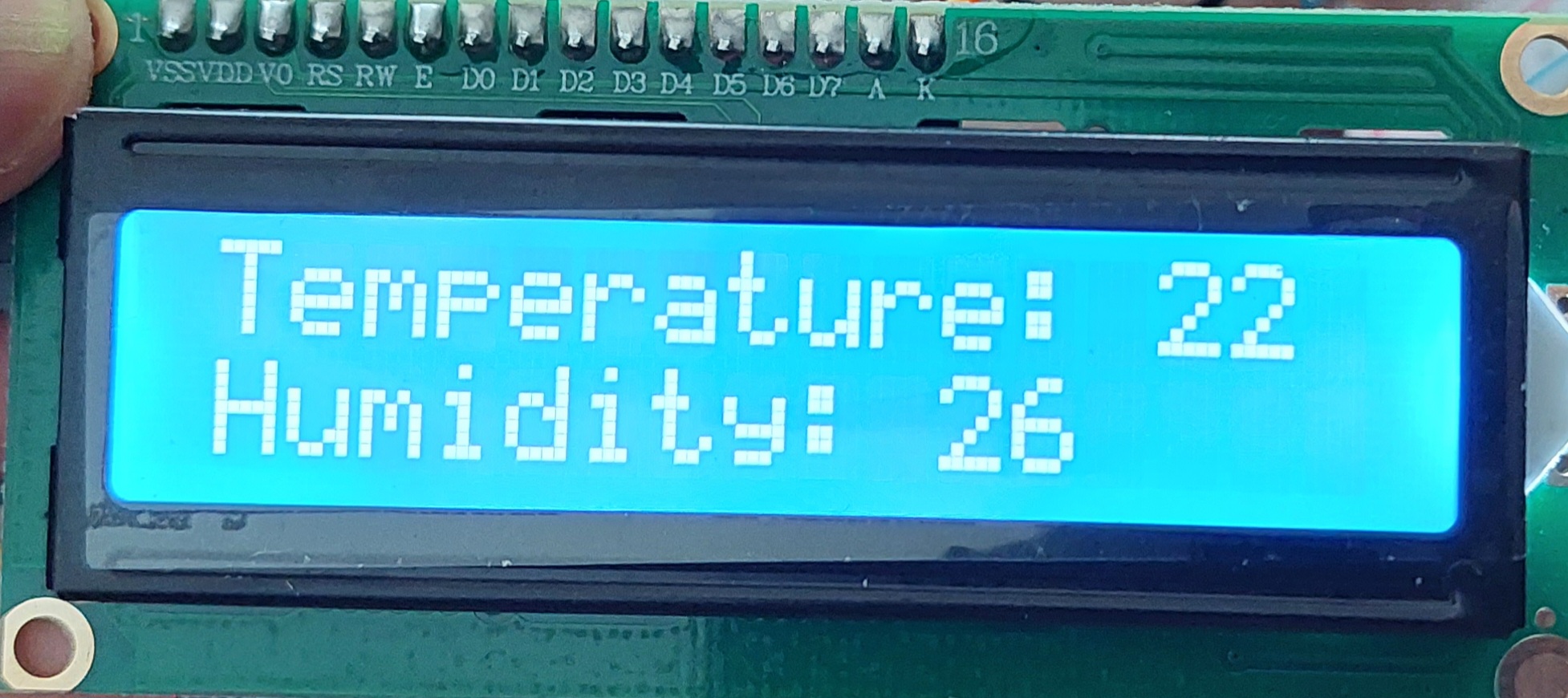
Feel free to take a look at the full source code